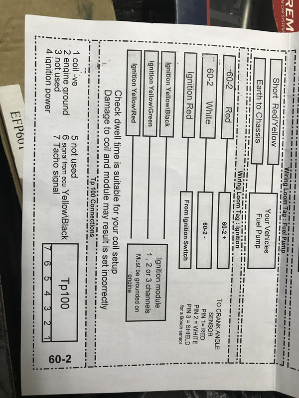
Tp100 Wiring Diagram efcaviation design tp100 wiring diagram phptp wiring diagram diagrams facbooik with template 7 diagram diagrams tarako citroen berlingo radio mulliveemasin mysoda tp frog ee wiring gotech pain the volkswagen club of south africa afabqqe coil mashups bosch ignition module electronic ford Tp100 Wiring Diagram dk tp100Aftermarket TP100 Ignition Module of High Quality built by Dicktator with high qulaity electronic IGFET components These Modules have no internal electronic rev limiter such as the VW TP100 Modules and are compatible with any engine management system, aftermarket or standard (for eg Bosch MP9) Reference DKTP100 Step 1 Locate Ignition Module To locate the ignition module, refer to a wiring diagram for your vehicle's particular make and model As you might guess, the placement can change based on the type of vehicle, so it is important to have the correct diagram or you will be practically going in blind
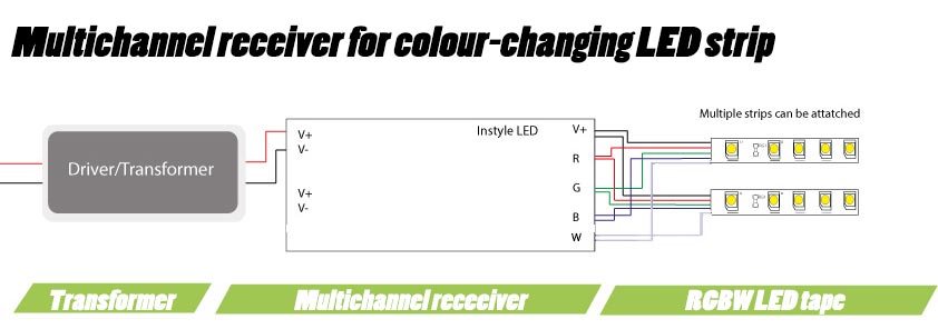
Led Wiring Guide How To Connect Striplights Dimmers Controls
Tp 100 module wiring diagram
Tp 100 module wiring diagram-Listed below is the vehicle specific wiring diagram for your car alarm, remote starter or keyless entry installation into your Toyota T100This information outlines the wires location, color and polarity to help you identify the proper connection spots in the vehicle Tp100 wiring diagram Called a friend over with his cti i tried my module on his car and it works fine Vw tp100 wiring diagram vw tp100 wiring diagram vw tp100 wiring diagram vw tp100 wiring diagram vw tp100 wiring diagram vw tp100 wiring diagram vw tp100 wiring diagram


Dicktator Management Wiring Coil Wiring And Module Wiring Youtube
Most of the wiring in the harness has been preterminated to the proper connector and all wire is rated at 125°C and has been GM colorcoded These fuel system harnesses have been divided into three major groups ENGINE GROUP Includes wiring Tp100 Wiring Diagram Vg30e Engine Begeboy Source Tp 100 Wiring Diagram Atimasrif Tator Single Coil Ignition Module Incl Plug Pins Ignition Modules Sel Electric Tp100 Wiring Diagram Block For Closed Loop Control System M Au Delice Limousin Fr Tp100 Wiring Diagram 00 Ford 50 Fuse Tekonshaii Corolla Waystar Fr Ezk Ipdown NetFamiliarize yourself with the PCM connectors, wire color and pin locations Enclosed is some wiring diagrams of the factory harness and a power module system diagram Diagrams for the 92 and 93 Corvette PCMs are not included but tech support is available via email Please be patient with email response I
Capacitors to operate Refer to the enclosed wiring diagrams Capacitors and relays must be sized for the specific motor Capacitors are sized based on ideal conditions The run capacitor may need to be resized to match the available field voltage Each cap kit shipped is supplied with a wiring diagram and start up procedure Pg 3 Variety of pt100 sensor wiring diagram A wiring diagram is a streamlined conventional pictorial representation of an electric circuit It shows the parts of the circuit as streamlined forms, and the power and signal links in between the devicesTP100 Ignition Spark Module R R TP100 Ignition Spark Module quantity Add to cart Category IGNITION
602 Trigger Kit Diagram Driveshaft Speed Sensor Kit Diagram Oil/Fuel Pressure & Flex Fuel Diagram 075psi Pressure Sensor Diagram 0100psi Pressure Sensor Diagram 0150psi Pressure Sensor Diagram 0250psi Pressure Sensor Diagram psi Pressure Sensor Diagram TPS Wiring DiagramTp100 Ignition Module Wiring Diagram 1990 Dodge Ram 50 2 4 Will Not Fire I Have Replaced The Distributor What Do I Need To Check And How I Removed The AGE 16v Wiring Diagrams Dictator 60With Lumina Coils If youre using TP1you can get a plug at Motolec Oct ok gotech wiring diagram study see use no tp1and directly fires the coil mrgreen thumright thumleft as mrturbo and dictator does and All engines must have a After market ignition systems are not allowe TP 1is allowed RR (D


Dicktator Management Wiring Coil Wiring And Module Wiring Youtube


2
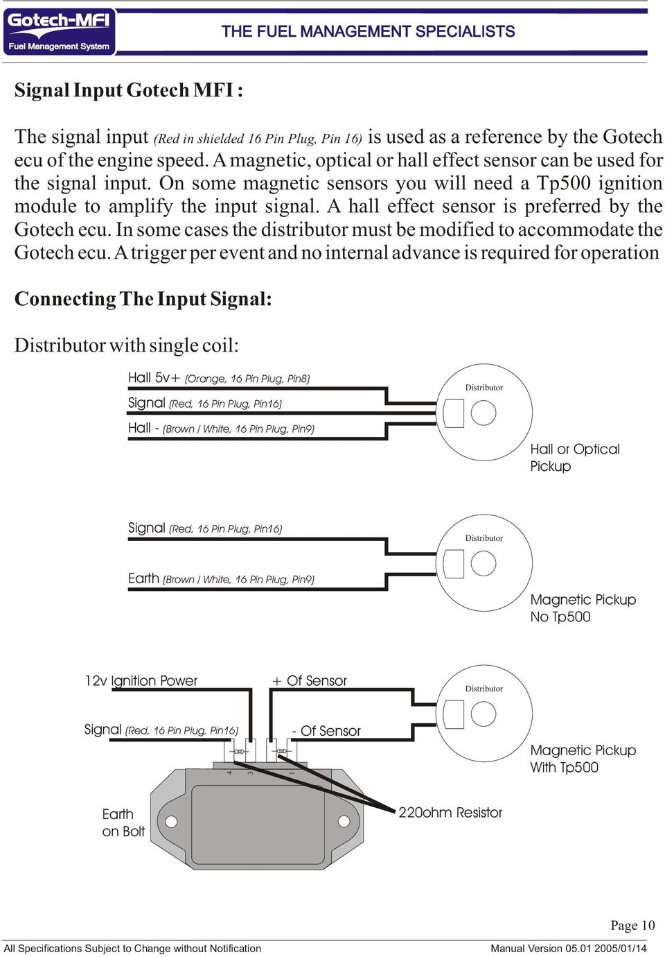
OE quality parts from top original equipment and aftermarket manufacturers The finest quality at a great price $ Genuine® TPMS Control Module (36 10 6 796 604) 0 # mpn TPMS Control Module by Genuine® Genuine is here to give you the ultimate in quality and reliability at a cost you can affordSubwoofer Wiring Diagrams Step #1 – Choose the # of subwoofers you will wire in your system from one amplifier output Step #2 – Specify 2 or 4 ohm single voice coil OR 2 or 4 ohm dual voice coil subwoofer (s) The Subwoofer Wiring Diagram tool will then display two wiring options with the final impedance at the amplifier Vw coil wiring mk 3 diagram aircooled south africa tp100 9006 hid dictator 60 2 install bmwfanatics thunderchild full tator single ignition module mfi instructional manual version pdf timer instructions Vw Coil Wiring Mk 3 Diagram 142 Threat Convert To Electronic Ign Page 2 Aircooled Vw South Africa Tp100 Wiring Diagram 9006 Hid


Tp 700 Instruction Manual Detcon


Www Trane Com Content Dam Trane Commercial Global Products Systems Equipment Unitary Variable Air Volume Vav Svx07f En 0409 Pdf
TYPICAL INSTALLATION – MODEL TP2 The TP2 senses the electical power input to a motor (horsepower) The Output is a 4 Milliamp LOOP POWERED analog signal proportional to power 505 368HP 755 552HP 1005 736HP 1505 110HP 05 147HP 3005 221HP 4005 294HP 5005 368HP 7/07TIM Scully Truck ID Module for Scully Intellitrol/VIP system compatibility Temperature Range 40° to 140° F (40° to 60° C) Materials Epoxy encapsulated Dimensions Shown on diagram Approvals Factory Mutual (FM), for use in Class 1, Division II, Group D hazardous locations in the US and CanadaA wiring diagram is a straightforward visual representation of the physical connections and physical layout of your electrical system or circuit It shows how a electrical wires are interconnected which enable it to also show where fixtures and components may be coupled to the system
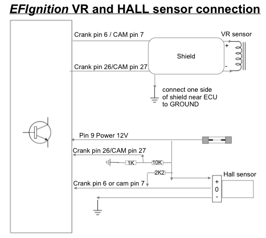


Wiring Loom Efignition


Ignition Modules Diesel Electric
2 3 4 This tutorial will help you to diagnose a bad ignition control module (ICM) causing a misfire condition on your VW 18L Passat (New Beetle, Jetta, Golf) It will also help you to troubleshoot a bad CoilOnPlug (COP) ignition coil One of the most common failures with this type of ignition control module (ICM) is a misfire condition 12way (Row) SPN = 12 X 1SP= 12Nos (Module) of single pole MCB as outgoing feeders Normally single phase distribution is mainly used for small single phase loads at house wiring or industrial lighting wiring 2) TPN Distribution Board (Incoming, Outgoing) 4way (Row) TPN = 4 X TP= 4nos of 3pole MCB as outgoing feeders =12 No of single pole MCB I need help with the wiring for the TP100 with the harness, I dnt want to burn the module or anything else Three wires , one red, one blue and one green and white that has an eye terminal on it Correct me if I am wrong here Red will go to the positive of the coil, blue will go the negative and the green&white wire ????


Dicktator Installation Training Package


Http Cgproducts Johnsoncontrols Com Met Pdf Pdf
Asv Wiring Diagram Wiring Diagram Schemes • asv wiring diagram wiring diagram will be a thing u rh exploreandmore co uk Dynatek Asv Rc Wiring schematronorg Free Download Here ASV RC Track Skid Steer Ats Equipment ELECTRICAL WIRING DIAGRAM Specified torque N–m ( kgf–cm, 7 ft–lbf) AIR CONDITIONING SYSTEM – AIR Asv Rc Wiring rtd pt100 3 wire wiring diagram – A Beginner s Guide to Circuit Diagrams An initial look at a circuit layout might be complicated, yet if you could check out a subway map, you can check out schematics The function coincides receiving from point A to aim B Literally, a circuit is the path that permits electricity to circulation If you TP 100 module wiring Search Advanced search 6 posts • Page 1 of 1 16V Dub Cadet I need some help with my module wiring I'm not getting spark from coil wire Called a friend over with his CTi, i tried my module on his car and it works fine it seems like diagram for gotech management Module, coil and dizzy works fine when tested


96 V8 Csw Ignition Module


Q Tbn And9gcq24zmmaopkmsslmuskj Oxkfebydvehd1fh3vst4q2xftmaxqj Usqp Cau
An ignition module is the component in electronic ignition systems that functions as the contact breaker for the coil or coils In most basic terms, an ignition module is an electronic replacement for old, mechanical contact breakers like ignition points These components are also referred to as "ignition control units" and "ignitorsDescription Pt100 3 Wire Circuit Diagram 3 Wire Rtd Connection Wiring Diagrams throughout Pt100 Wiring Diagram, image size 473 X 291 px, and to view image details please click the image Here is a picture gallery about pt100 wiring diagram complete with the description of the image, please find the image you need We hope this article can help in finding the information youDepending on the type of security your vehicle uses, you'll need to use 45 of this units wires Most of my experience with this unit has been with GM's Passlock II but I have also done a few transponder style installs Don't let the terminology intimidate you, as the
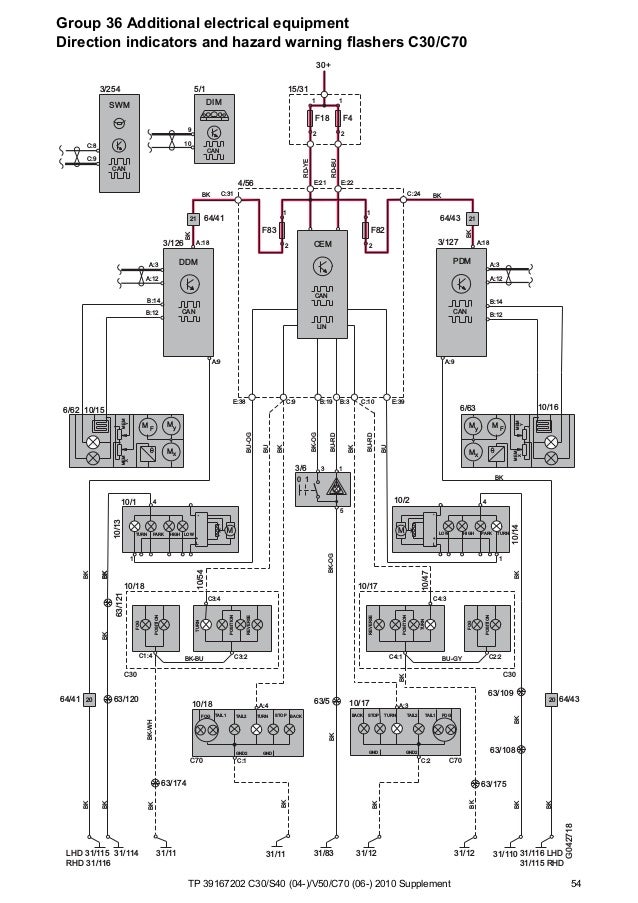


Tp 10 C30 S40 V50 C70 Supplement Wiring Diagram


Tp 100 Wiring Diagram Atimasrif
16 The measurement between wire A and wire B will be over 100 ohms 17 The measurement between wire A and wire C will be the same 18 The measurement between wire B and wire C will be low, just the resistance of the wire itself 19 You will now have identified which wire is which Now connect them to the appropriate3Ø WIRING DIAGRAMS 1Ø WIRING DIAGRAMS Diagram ER9 M 3~ 1 5 9 3 7 11 Low Speed High Speed U1 V1 W1 W2 U2 V2 TK TK Thermal Overloads TWO SPEED STAR/DELTA MOTOR Switch M 3~ 010V V 415V AC 4mA Outp uts Diagram IC2 M 1~ 240V AC 010V Outp ut Diagram IC3 M 1~ 010V 4mA 240V AC Outp uts These diagrams are current at the time of publicationPT100 Temperature Sensor Wiring Diagram 3 wire Pt100 RTD Sensor Wiring System The addition of a third wire, connected to one side of the measuring element, helps to compensate for the lead resistance It is very important that each of the three wires used in the measuring circuit are equal in terms of both conductor size and length


Fieldbus Connectivity For Drives Connectivity Abb


1
Pt100 (platinum 100 ohm) and Pt1000 (platinum 1000 ohm) resistance temperature devices are the most commonly used design with the 4 Wire configuration Temperature Operating range for a 4 Wire RTD is the same as the 2 or 3 wire configurations, meaning 3°F to 1,562°F (196 to 850°C) depending on the design selectedThe GREEN/WHITE wire labeled "Fan Relay Trigger" is a trigger wire for a relay only and will not be able to run a fan by itself Speedometer If you are using a Vehicle Speed Sensor (VSS), the GRAY wire labeled "Speed Output 4000 PPM" is an output from the ECM and may be connected to an electronic Speedometer Tp100 wiring diagram solar diagrams for homes tekonshaii corolla waystar fr thunderchild dictator 60 2 install bmwfanatics timer instructions full version hd quality outletdiagram varazzeoutdoor it 8v tator without the volkswagen club of south africa mfi instructional manual pdf free nissan ford ignition control module sharediagrams tacus single coil
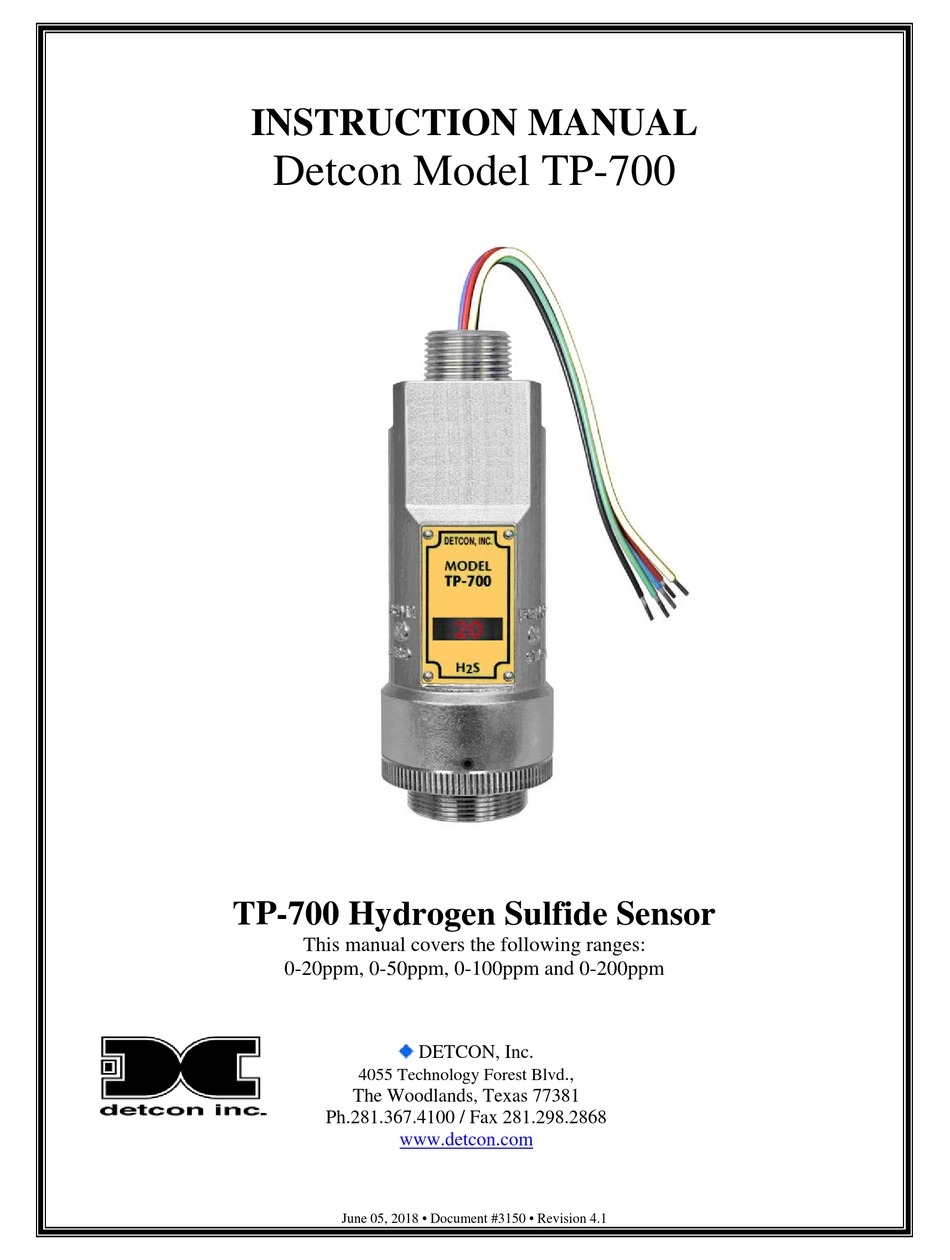


Detcon Tp 700 Instruction Manual Pdf Download Manualslib


Detcon Tp 624c User Manual
Text temperature measurement over a wide range with controllers equipped with a Pt100 sensor input, eg , Technical design The Pt100 temperature sensor is fitted with a platinium measuring element with a , 1 797 FTTP/100 FTTP/400 Immersion temperature sensor for HVAC systems Immersion temperature sensor for heating, ventilation and airPLUG & PLAY HARNESS PLUG N PLAY HARNESS; 1 Common Throttle Position Sensor (TPS) wiring diagram (wire color, terminalToyota T / I need a wiring diagram for I need a wiring diagram for a Toyota t pickup Help please ( Toyota T) Micah Keener in Edgefield, SC on August 11, Sign in to Answer Throttle Position Sensor Apr 05, I need a full wiring diagram from a T 4x4 A/T


Ignition Control Module Wiring Help Ford Truck Enthusiasts Forums


Calameo 05 Supplement S60 S60r S80 V70 V70r Xc70 Xc90 Wiring Diagram
The most common type PT100 has a resistance of 100Ω at 0°C and 1384 ohms at 100°C RTDs come in 2wire, 3wire or 4wire versions The 2wire RTD signal is affected by the distance to the controller, but 3wire or 4wire RTDs can compensate for line losses Unlike thermocouples, special connection cables are not very necessary for PT100 Pt100 rtd sensor pinout features uses guide datasheet colour codes iec difference between 2 wire 3 and 4 s wiring tc inc general purpose thermocouple online com in or connection wika blog temperature transmitter e k b t j n r type ato txblock usb for configurations diagrams probes thermocouples sensors auber instruments control solutions home industry rtd pt100 3 wire wiring diagram – What is a Wiring Diagram?


Www Careluk Com Documents 0 2b 1e00eb 0f73 490b 8d81 0d63ce4e1567 Version 1 1


1pc Touch Lighting Control Mt 1001 100v 1v 150w 60hz Dimmer Halogen Tungsten Led Light W Wire Nuts Switches Aliexpress
One sensor structure can include also several Pt100 resistances 1, 2 or 3 × Pt100 (most common is 1 × Pt100) For different measuring circuits the resistance element can be produced in different versions 2, 3 or 4wire connection (most accurate is 4wire)There are 2 wiring methods for the RTD module and PT100 temperature sensors — twowire and threewire connections When wiring with two wires, first jumper across A1 and B1and and B2 respectively, then connect PT100 sensors and to the RTD module according to the following diagram on the left (Note A1B1, B2 and C1C2Ignition Module SAAB 93 90 2 Ignition Module Indirect Details» BOSCH 0 227 100 139 Ignition Module BOSCH 0 227 100 139 Ignition Module Indirect


Dictator Tp100 Wiring Diagram Sweetskeleton39


Zing Ear Tp 01 Zh Touch Lamp Light Dimmer Switch Control Sensor Amazon Com
When connected to the amplifier, the smart amp will measure the voltage across the RTD and also across the wire pairs For example, here's the approximate resistances of a 4Wire PT100 RTD at 0 ° C (for a PT1000, the middle resistance would be (1002 Ω rather than 102 Ω) (Remember that the middle resistance 102 or 1002 Ω will vary withBASIL Networks offers Design and Development services BASIL Networks is multidisciplined, addressing hardware, software and OEM DFM product development in the areas of DC to RF, high speed analog, digital hardware design, embedded processor design, software design Visual Studio, Windows Linux A/D/A Data acquisition CAM, ATE systems, process control system andThe distributor handles several jobs Its first job is to distribute the high voltage from the coil to the correct cylinder This is done by the cap and rotor The coil is connected to the rotor, which spins inside the cap The rotor spins past a series of contacts, one contact per cylinder As the tip of the rotor passes each contact, a highvoltage pulse comes from the coil


Www Bosch Motorsport Com Content Downloads Raceparts Resources Pdf Data sheet Ignition Module Im 3 2 Pdf
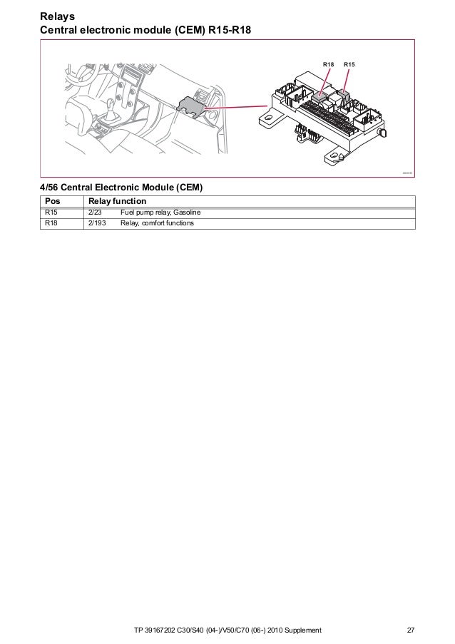


Tp 10 C30 S40 V50 C70 Supplement Wiring Diagram
Collection of pt100 sensor wiring diagram A wiring diagram is a simplified conventional pictorial representation of an electrical circuit It reveals the components of the circuit as simplified forms, and the power as well as signal links in between the gadgets Based on the information of the suggested S7300 Module Datamanual, it looks like you should be connecting your SM3311KF01 module to the 2wire RTD through pins M and M, with a short from M to S (pins 25, 24 and 23 in Channel 4, in the example) They also add the following note about module signal groundingARC100 Addressable Fire Panel Wiring Diagram Type of Circuit Voltage Type Power Type AC Connection High Voltage NonPower Limited side of each module The maximum wiring resistance between an AIB/SCI shall be less than 10 ohms and the total resistance must be below 50 ohms The maximum wiring resistance shall be calculated based on 01 ohm


Ignition Module Tp100 Vw Fox 1 3 1 6 1 8 1987 On Speedquip
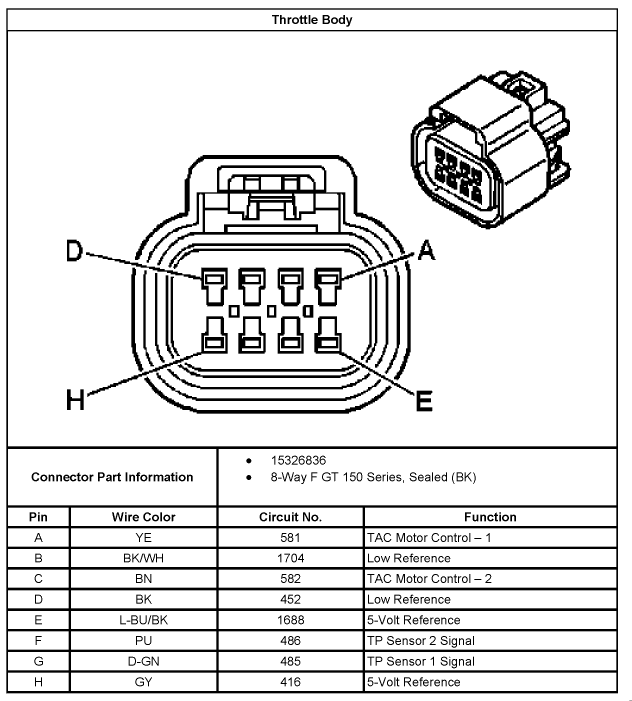


5 3 Wiring Harness Wiring Diagrams Here Ls1tech Camaro And Firebird Forum Discussion
Make/Model specific wiring diagrams are widely available and free!FITMENT CENTRE TURBO CONVERSIONS STAINLESS STEEL FABRICATION;Module to the 10"/19" media chassis (up to 15 units) for a TP and Fiber combined networks at a central wiring closet Please contact with your sales representative for more about the 10/19" media chassis 3 Checklist Your FT80X carton should contain the following items The Fast Ethernet Bridge Converter
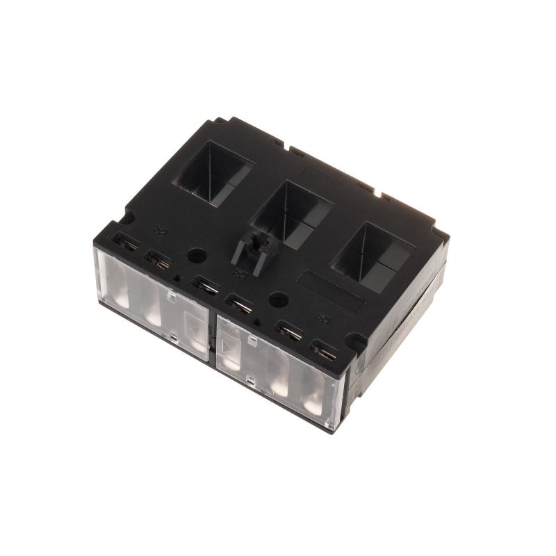


Current Transformer Tp 100


Mk3 Cli Rev Counter And Oil Light Connected To Tsz H The Volkswagen Club Of South Africa
While a separate FTA of a given type is required to handle varying field wiring signal levels, identical I/O Processors can usually be used This I/O approach simplifies system hardware selection and minimizes spare parts requirements For example, one Digital Input Processor can handle 24 Vdc, 1 Vac, 125 Vdc


Ignition Module Tp900 Vw Opel Audi Bmw Speedquip


Dicktator Connection Diagrams September 09 Pdf Ignition System Fuel Injection


Ford Ignition Module Tis321 Taiwan Ignition System Co Ltd Ignition Coil Crank Angle Sensor Ignition Module Electronic Ignition Engine Ignition Coil Cdi Ignition Distributor Module Cdi Ignition Module


6 Wiring Diagram Coil Transmission Control Module Wiring Diagram 6 Wiring Diagram Memo 21 Wiring Diagram 76 6 3 D6r2 Wiring Diagram 6 Pdf Document


Www Emerson Com Documents Automation Manual Tx Series Valve Controllers Topworx En 9 Pdf


Www Careluk Com Documents 0 2b 1e00eb 0f73 490b 8d81 0d63ce4e1567 Version 1 1
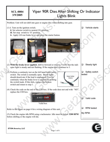


Scl0004 Manualzz


Vw Passat B5 1 8l Engine Aeb Motronic Mfi Eng Manualzz


Www Siemens Com Download A6v


Http S7d2 Scene7 Com Is Content Watscocom Gemaire Rcd Parts Tp Nrh01 A Article En Ii Pdf


Http S7d2 Scene7 Com Is Content Watscocom Gemaire Rcd Parts Tp Nrh01 A Article En Ii Pdf


Www Nexcobot Com Download File 5e35e341aaaf1e75c5bafcad5b5b6648f81a6c40c50feaa6b513fd2df46dc4e460e8f01d0af8f330cdaa3e3fa3da1ddb7ab1819b87e241be4130f8134fabbdd7f54aa2aa949fbea3db12f9dae3f5c2bc8ac8b8734f2114a1e9e818dc8d3d2cc


Dicktator Issues Help Please The Volkswagen Club Of South Africa


Dicktator Tp100 Spark Module


Www Elliottelectric Com Media Tm7556 Pas 4 0 Installationsheet Pdf


Rev Counter Issues The Volkswagen Club Of South Africa


Part 1 How To Test The 1 8l Vw Ignition Control Module And Ignition Coils


Www Teledynegasandflamedetection Com Sites Teledynegasandflamedetection Com Files Product Specs Olct700 26 710 Tp User Manual En Olct 700 26 710 Tp Rev C 1 English Pdf


Gotech Mfi Manual Manualzz


Download Service Manual Kohler Generator10eg 13eg 15eg By Heydownloads Issuu


Dicktator Connection Diagrams September 09 Pdf Ignition System Fuel Injection


Power Esp32 Esp66 With Solar Panels And Battery Random Nerd Tutorials


Wouter S Page The Retro Society Of Reverse Engineering And Taking Things Apart


As P Installation


Led Wiring Guide How To Connect Striplights Dimmers Controls


Kteb 2c72 1 Tp Keystone Electronic Fluorescent Ballast


Tp 10 C30 S40 V50 C70 Supplement Wiring Diagram


Diagram Isuzu Bighorn Stereo Wiring Diagram Full Version Hd Quality Wiring Diagram Solardiagrams Hotelrigelcatania It


Ignition Modules Diesel Electric


Ezk Ipdown Net


Most Frequently Asked Questions About Tp Link Powerline Devices
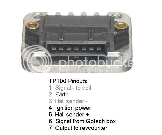


Tp100 Wiring Diagram Timer Instructions


1


Www Siemens Com Download A6v


Tp 100b Datasheet Pdf Mean Well Enterprises Co Ltd


Tp 10 C30 S40 V50 C70 Supplement Wiring Diagram


Wiring The Enc28j60 Ethernet Module On Arduino With Relay 14core Com


Http Cgproducts Johnsoncontrols Com Met Pdf Pdf


Dictator 60 2 Install Bmwfanatics


Ignition Modules Diesel Electric


Ignition Module Tp100 Opel Rekord 2 0 2 0se 19 On Speedquip


Led Wiring Guide How To Connect Striplights Dimmers Controls


Diagram Valley Center Pivot Wiring Diagram Full Version Hd Quality Wiring Diagram Solardiagrams Hotelrigelcatania It


Wiring Diagram For Installing A Signal Converter In Order To Make A Tachometer Work With A Magneto Alkydigger Technical Info


I Believe The Thing I Need Is A Wiring Diagram For A 1998 Olds 3800 Series It Has A No Spark Condition It Does Have


Http Files Pranakorntech Com Honeywell Honeywell morley Honeywell morley ul Manual morley ul Ns Sh 0005 Slc Wiring Manual Pdf


Kteb 2 1 Tp Emi Keystone Ballast


What Does Each Wire From The Distributor Do An Ignition System Diagram Would Be Fantastic


27 98 Chevy Silverado Ideas 98 Chevy Silverado Chevy Silverado Silverado
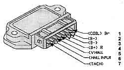


Thunderchild


Preview Of Electrical Wiring Diagram 05 Nubira Lacetti 2 Ecm Engine Control Module Mr 140 Pdf Electrical Connector Fuse Electrical


How To Wire Mid 1970s Through Mid 1980s Ignition System With A Gm Ignition Module Mopar Forums
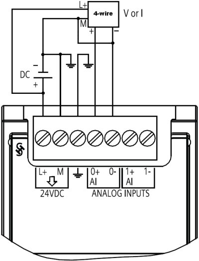


How Do You Connect A Sensor To The Analog Signal Modules Of The S7 10 S7 1500 An Id Industry Support Siemens


Tp 100 Conversion For 2 And 3 Wire Distributors Wiring Len Flickr


1


Zing Ear Tp 01 Zh Touch Lamp Light Dimmer Switch Control Sensor Amazon Com


Tp100 Vw Conversion Wiring Len Gerber Len Gerber Flickr


5 Pins Cdi Connection And Wiring Diagram alog Tutorial Part 2 Youtube
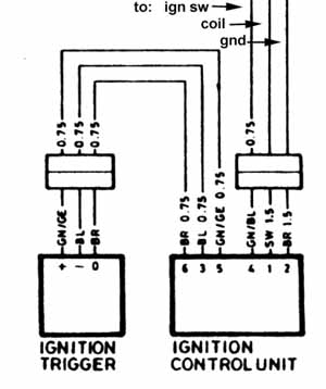


Thunderchild
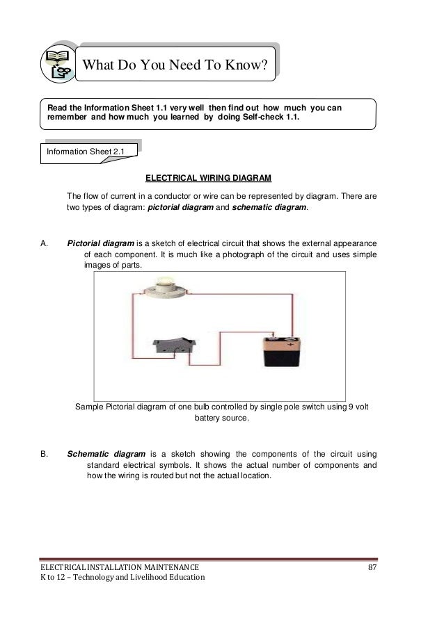


K To 12 Electrical Learning Module


Ford V6 Ignition Module Wiring African Muscle Cars Forum


Ignition Control Module Wiring Help Ford Truck Enthusiasts Forums


Tp100 Ignition Module Dicktator


Module Circuits Wiring Diagram Youtube


Dicktator Wiring Double Check The Volkswagen Club Of South Africa


Coil Induction Wiring Diagrams Youtube


Diagram Throttle Body Wire Diagram Full Version Hd Quality Wire Diagram Solardiagrams Hotelrigelcatania It
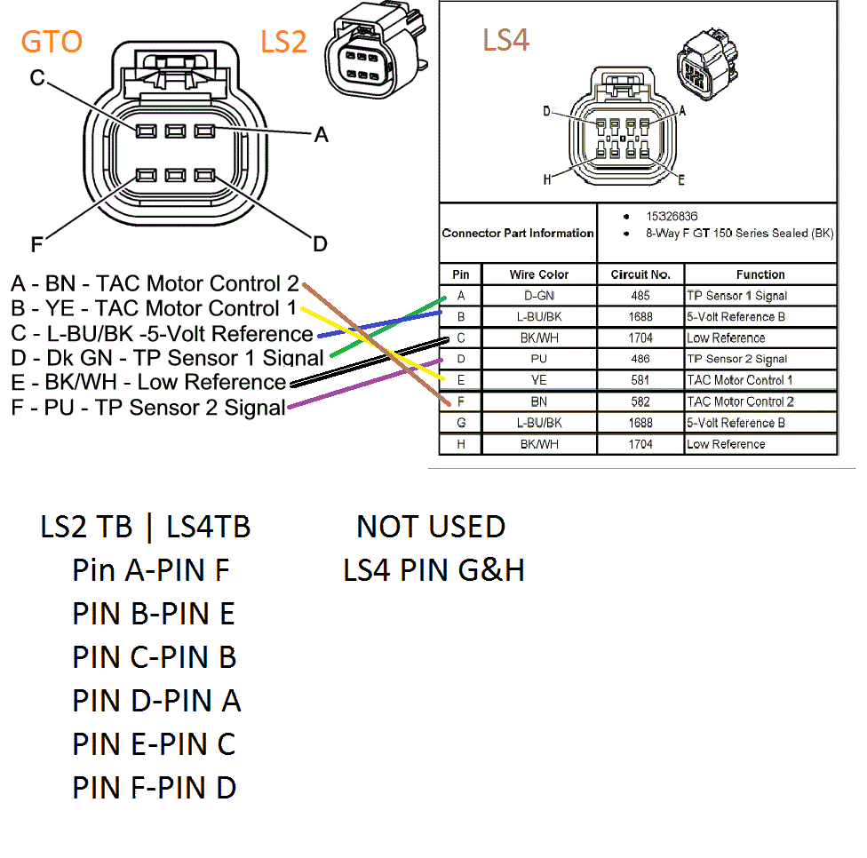


Diagram Throttle Body Wire Diagram Full Version Hd Quality Wire Diagram Solardiagrams Hotelrigelcatania It


Www Nexcobot Com Download File 5e35e341aaaf1e75c5bafcad5b5b6648f81a6c40c50feaa6b513fd2df46dc4e460e8f01d0af8f330cdaa3e3fa3da1ddb7ab1819b87e241be4130f8134fabbdd7f54aa2aa949fbea3db12f9dae3f5c2bc8ac8b8734f2114a1e9e818dc8d3d2cc
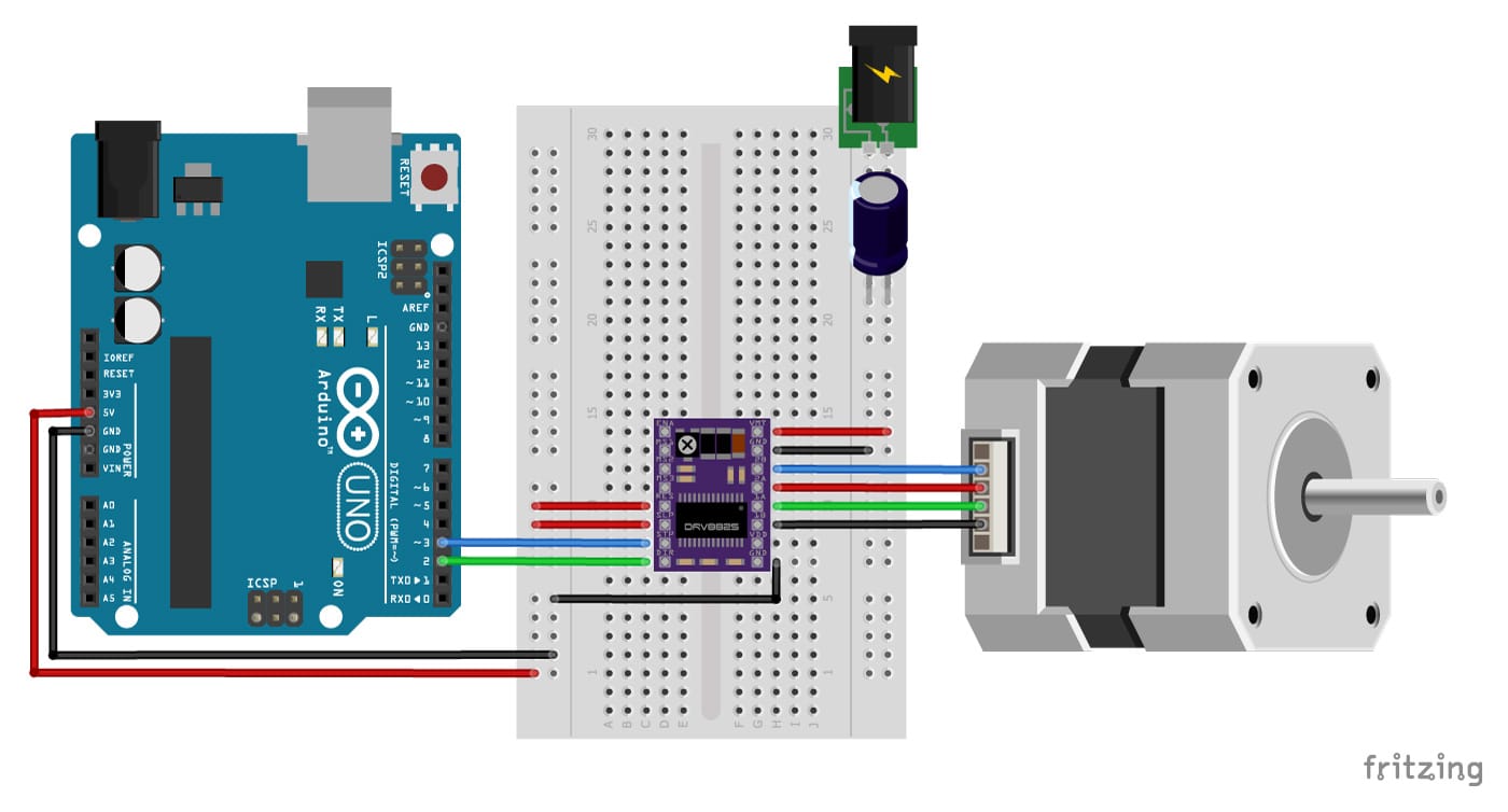


Stepper Motor With Drv85 And Arduino Tutorial 4 Examples
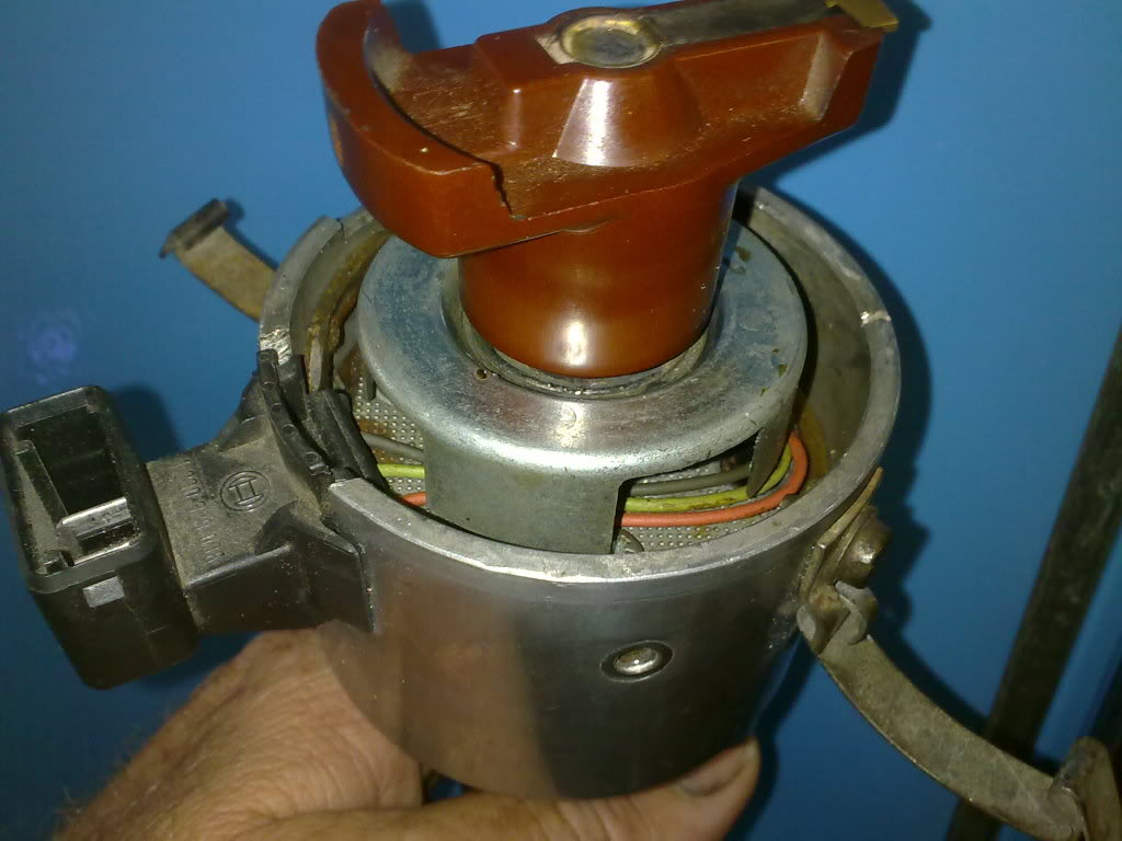


Convert To Electronic Ign Page 2 Aircooled Vw South Africa


How To Wire Mid 1970s Through Mid 1980s Ignition Systems Retrofitting Electronic Ignition On Vehicles That Originally Had Points Allpar Forums


8pin Tps Module Color Wire Diagram Hyundai Forums


Tp 08 C30 S40 V50 C70 Wiring Diagram Pdf


Volkswagen Golf Jetta 2 0l Engine Aeg Motronic Mfi Eng Manualzz


Mfi Instructional Manual Version Pdf Free Download


0 件のコメント:
コメントを投稿